


yo we building our own Glucometer from scratch.
This is gonna be a long article so hold on.
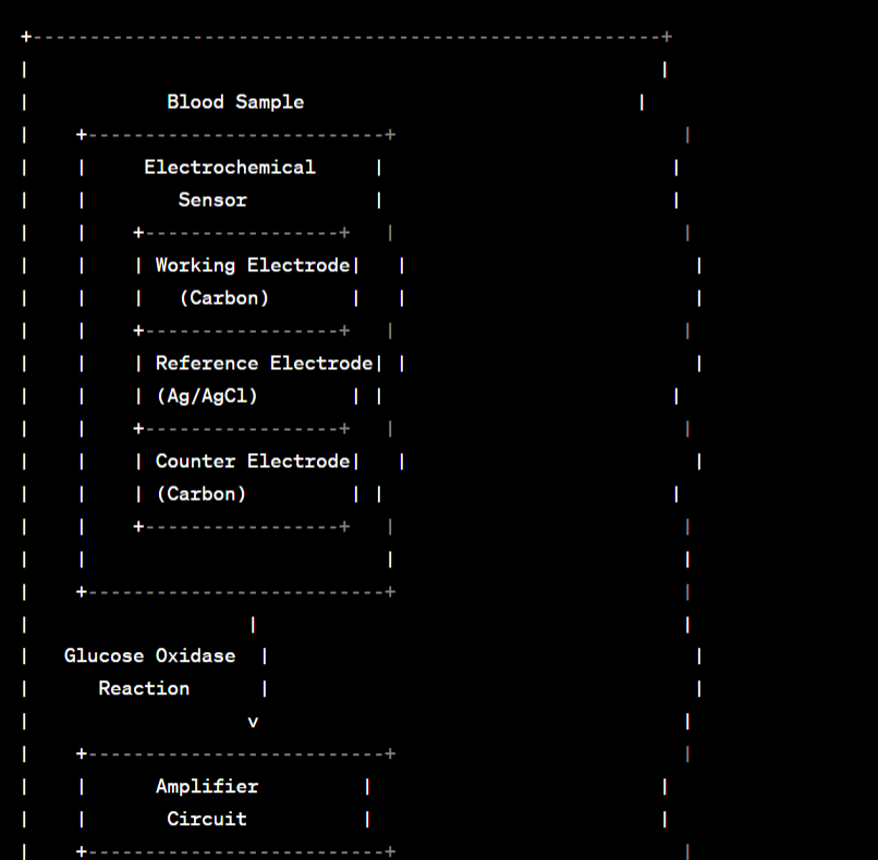
Abstract Circuit Diagram / Blueprint:
Fun Theory:Introduction:
Ladies and gentlemen, gather 'round because today we're about to dive headfirst into the sugary world of glucometers! Picture this: you've just had a scrumptious meal of pizza, pasta, and pancakes (yes, you're living on the edge), and you're curious if your blood sugar levels resemble a roller coaster ride or a gentle carousel spin. Fear not, for the trusty glucometer is here to save the day – and it's not just any ordinary gadget; it's a modern-day Sherlock Holmes for your bloodstream!
Now, you might be wondering, "What sorcery is at play inside this tiny device?" Well, dear reader, allow me to unravel the mystery with a sprinkle of humor and a dash of quirky analogies.
Principle of Glucometers:
Imagine your bloodstream as a bustling city, with glucose molecules zooming around like caffeinated commuters trying to catch their trains. But how do we measure the concentration of these glucose molecules in our blood, you ask? Enter the glucometer, the ultimate blood sugar detective!
At its core, a glucometer operates on a principle that's as simple as baking cookies – it's all about electricity! Just like how you can't bake cookies without an oven, you can't measure blood sugar without some nifty science.
Glucometers use a technology called amperometric biosensors. Sounds fancy, doesn't it? Think of these biosensors as tiny glucose-eating Pac-Man characters strategically placed on a glucose-infested game board (your blood sample). They have a particular fondness for glucose, and when they gobble it up, they produce electrical signals as a form of gratitude.
Now, imagine you're playing a game of "Whack-a-Mole" at the arcade. Glucose molecules are the pesky moles popping up, and the biosensors are your trusty mallets. When a glucose molecule dares to show its sugar-coated head, the biosensors give it a little tap, and zap! They generate tiny electrical currents.
But here's where the magic happens: the more glucose molecules there are in your blood, the more "whacking" the biosensors do, and the stronger the electrical signal they produce. This signal is like a report card for your blood sugar levels, telling you whether you're in the "sweet spot" or venturing into "sugar rush" territory.
So, in essence, a glucometer is like a glucose whisperer, listening to the whispers of the sugar molecules in your blood and translating them into a digital language that you can understand. It's like having a translator for a secret sugar society!
Now that we've peeked into the glucometer's secret recipe for measuring blood sugar, let's take a closer look at how it works its sugary sorcery in more detail. Hold onto your sweet tooth, folks, because we're about to get technical and whimsic.
Simple OOGA BOOGA Explanation:
when blood touches that strip, strip reacts with blood and produces current, the machine reads the current using smart maths and give you a reading of glucose level.
more glucose in your blood, more current gets produce, more is the reading
Detailed Principle of Glucometers:
Before we dive into the intricate workings of glucometers, let's establish the fundamental principle upon which these devices are built. At its core, a glucometer is designed to measure the concentration of glucose in a person's blood. This is achieved through a process known as glucose oxidase-based amperometric sensing.
1. Glucose Oxidase-Based Sensing: The cornerstone of glucometer technology is an enzyme called glucose oxidase. This enzyme is highly specific to glucose and is crucial in the process of glucose measurement. Here's how it works:
When a blood sample is applied to a test strip, it interacts with glucose oxidase, which converts glucose into gluconic acid and hydrogen peroxide. This reaction is specific to glucose, ensuring accurate measurements.
The produced hydrogen peroxide is then detected using an electrode, typically made of a noble metal like platinum or gold. The concentration of hydrogen peroxide is directly proportional to the amount of glucose in the blood sample.
2. Electrochemical Sensing: The heart of the glucometer lies in its ability to convert the chemical reaction between glucose and glucose oxidase into an electrical signal. This is achieved through electrochemical sensing, a process that utilizes the principles of amperometry.
An amperometric sensor measures the current flow between two electrodes (working and reference electrodes) in the presence of a specific electroactive species (in this case, hydrogen peroxide).
As the concentration of hydrogen peroxide varies according to the blood glucose level, the resulting current also changes proportionally. This current is then converted into a numerical value that is displayed on the glucometer's screen as the blood glucose level.
Detailed Working of Glucometers:
With the principle of glucometers established, let's delve into the detailed working of these invaluable devices:
Sample Application: The user starts by pricking their fingertip to obtain a small blood sample. This sample is then applied to a disposable test strip, which contains the glucose oxidase enzyme.
Chemical Reaction: The blood interacts with the glucose oxidase on the test strip, leading to the conversion of glucose into gluconic acid and hydrogen peroxide. This chemical reaction is specific to glucose and occurs within a matter of seconds.
Electrochemical Sensing: The test strip contains the working and reference electrodes, separated by a membrane. The hydrogen peroxide produced in the reaction diffuses to the working electrode. Here, it undergoes an electrochemical reaction that generates a current.
Current Measurement: The generated current is proportional to the amount of hydrogen peroxide, which in turn is directly proportional to the glucose concentration in the blood sample.
Digital Display: The glucometer's internal electronics process the current signal, convert it into a numerical value, and display it on the device's screen. This numerical value represents the user's blood glucose level
Steps for Building in Lab:
`Disclaimer:: Lots of the values I got are from internet pdf's and various blogs I read, so they could miss match, but I guess you would have to try to find if they work hehe!`
Step 1: Designing the Glucose Oxidase-Based Sensor
1.1. Select a Suitable Electrode:
- Choose a working electrode material, such as a 3 mm diameter gold electrode, for optimal conductivity and stability.
1.2. Coating the Electrode:
Prepare a glucose oxidase enzyme solution by dissolving 10 mg of glucose oxidase in 5 mL of phosphate buffer (pH 7.4).
Immerse the cleaned electrode in the enzyme solution for 30 minutes to allow for proper adsorption.
Rinse the electrode with distilled water to remove excess enzyme solution.
Let it air dry at room temperature for 2 hours to ensure enzyme immobilization.
1.3. Sensor Housing:
Design a cylindrical housing made of chemically inert plastic (e.g., polypropylene) with a diameter of 12 mm and a length of 40 mm.
Include a 2 mm diameter sample application port with a silicone gasket for sealing.
Step 2: Electrochemical Setup
2.1. Select Electrochemical Components:
Choose an Ag/AgCl reference electrode with a saturated KCl electrolyte.
Select a platinum wire counter electrode with a diameter of 1 mm.
2.2. Electrolyte Solution:
Prepare an electrolyte solution containing 0.1 M phosphate buffer (pH 7.4) and 0.1 M KCl for optimal ionic conductivity.
Ensure the electrolyte solution is freshly prepared and free of contaminants.
2.3. Electrochemical Circuit:
Design an electronic circuit:
Integrate a potentiostat with a working potential of -0.4 V vs. Ag/AgCl.
Incorporate a sensitive ammeter capable of measuring currents in the nanoampere range.
Provide a stable voltage source of 0.6 V to the working electrode.
Step 3: Electronic Components
3.1. Microcontroller:
Select a microcontroller, such as an Arduino Nano, with an ATmega328P microcontroller unit (MCU).
Utilize digital I/O pins for sensor interfacing and user input.
Include serial communication ports for data transfer and connectivity.
3.2. Analog-to-Digital Converter (ADC):
Integrate a 12-bit ADC (e.g., ADS1015) to convert the analog current signal from the electrochemical cell into digital data.
Set the ADC to a sample rate of 100 Hz for accurate measurements.
3.3. Display Unit:
Add a 16x2 character LCD display (e.g., HD44780) with an I2C backpack to conserve digital I/O pins.
Interface the display via the I2C communication protocol.
3.4. User Interface:
Implement a 4-button tactile keypad for user interaction and menu navigation.
Create an intuitive menu system with an LCD-driven user interface.
3.5. Power Supply:
Include a 9V DC power supply unit with voltage regulation to ensure a stable voltage source for the components.
Utilize voltage regulators (e.g., LM7805) to provide 5V and 3.3V power rails for the microcontroller and sensors.
Step 4: Calibration and Data Interpretation
4.1. Calibration Curve:
Prepare a set of glucose standard solutions with concentrations ranging from 0 mg/dL to 400 mg/dL.
Measure the electrochemical currents produced by the sensor for each standard solution.
Plot a calibration curve by correlating the current values to the known glucose concentrations.
Use linear regression to determine the calibration equation, e.g., y = 0.025x - 0.005, where y represents current (nA) and x represents glucose concentration (mg/dL).
4.2. Algorithm Development:
Develop a microcontroller algorithm that applies the calibration equation:
Read the current value from the ADC.
Use the calibration equation to calculate the blood glucose concentration.
Display the result on the LCD display.
Step 5: Safety and Testing
5.1. Safety Measures:
Ensure that the device complies with safety standards:
Implement electrical safety measures, including insulation and grounding.
Follow biohazard precautions for handling blood samples, such as wearing gloves and disposing of used materials properly.
5.2. Accuracy Testing:
Test the glucometer with blood samples of known glucose concentrations to validate its accuracy and reliability:
- Compare the glucometer's readings to the actual glucose levels using a reference method (e.g., lab-based spectrophotometry
Working of the glucometer circuit:
the circuit we build using the above steps, let's discuss how they work in theory.
Step 1: Sample Application
The user pricks their fingertip to obtain a small blood sample.
Using a capillary action or a micropipette, the user applies the blood sample to the sample application port of the glucometer's sensor housing.
Step 2: Electrochemical Reaction
Inside the sensor housing, the blood sample comes into contact with the glucose oxidase-coated working electrode.
The glucose oxidase enzyme catalyzes the oxidation of glucose in the blood sample to produce gluconic acid and hydrogen peroxide:
Glucose + Oxygen → Gluconic Acid + Hydrogen Peroxide
The amount of hydrogen peroxide generated is directly proportional to the glucose concentration in the blood sample.
The generated hydrogen peroxide then diffuses to the working electrode's surface.
Step 3: Current Measurement
An electrochemical cell is formed with the working electrode (enzyme-coated electrode), the reference electrode (Ag/AgCl), and the counter electrode (platinum).
The potentiostat, a component of the electrochemical circuit, maintains a constant potential difference between the working and reference electrodes (e.g., -0.4 V vs. Ag/AgCl).
This controlled potential difference drives the electrochemical oxidation of hydrogen peroxide at the working electrode. The oxidation process results in an electrical current flowing from the working electrode to the counter electrode.
The ammeter, another component of the circuit, measures this current. The measured current value is directly related to the concentration of hydrogen peroxide, which, in turn, correlates with the glucose concentration in the blood sample.
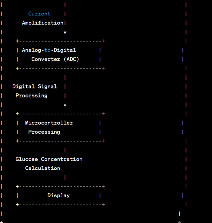
Step 4: Data Processing and Display
The analog current signal from the ammeter is converted into a digital signal by the analog-to-digital converter (ADC). The ADC's precision and sample rate ensure accurate measurements.
The microcontroller receives the digitized current data and applies the calibration equation established during the calibration process.
The calibration equation relates the measured current to glucose concentration (e.g., y = 0.025x - 0.005, where y represents current in nA, and x represents glucose concentration in mg/dL).
The microcontroller calculates the blood glucose concentration using the calibration equation.
The result is displayed on the LCD screen as the user's blood glucose level in mg/dL.
Sample Result:
based on artificial average values
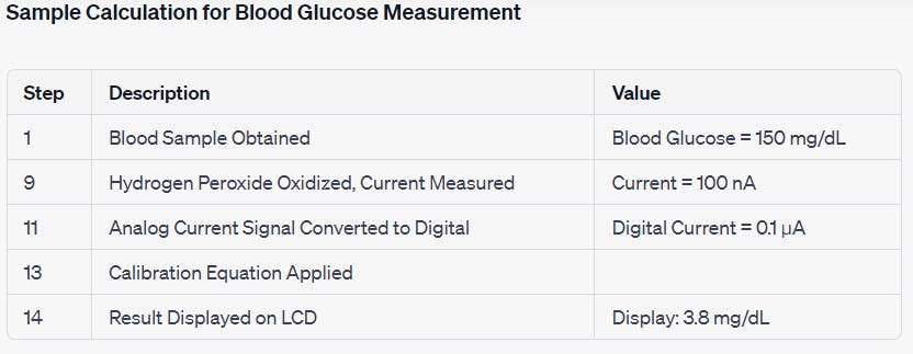
Explanation:
Blood Sample Obtained (Step 1):
- The user pricks their fingertip and obtains a blood sample with a glucose concentration of 150 mg/dL.
Hydrogen Peroxide Oxidized, Current Measured (Step 9):
Inside the electrochemical sensor, the blood sample undergoes an electrochemical reaction.
The glucose in the blood sample is oxidized to produce hydrogen peroxide.
The resulting hydrogen peroxide generates a current of 100 nA, which is measured by the sensor.
Analog Current Signal Converted to Digital (Step 11):
- The analog current signal of 100 nA is converted into a digital signal with a value of 0.1 µA by an analog-to-digital converter (ADC).
Calibration Equation Applied (Step 13):
- The glucometer uses a calibration curve or equation, determined during calibration with known glucose concentrations, to convert the digital current value into blood glucose concentration.
Result Displayed on LCD (Step 14):
- The calculated blood glucose concentration is displayed on the LCD screen, showing a reading of 3.8 mg/dL.
Calibration Equation:
The calibration equation is used to relate the measured current to blood glucose concentration. It's determined during the calibration process by measuring known concentrations of glucose and plotting a calibration curve.
In this example, we'll use a simplified linear equation for illustration:
Glucose (mg/dL) = (Digital Current - Offset) / Sensitivity, where:Digital Current = 0.1 µA (measured)
Offset = 0.005 (a constant determined during calibration)
Sensitivity = 0.025 (a constant determined during calibration)
Plugging in the values:
Glucose (mg/dL) = (0.1 µA - 0.005) / 0.025 ≈ 3.8 mg/dL
So, in this sample calculation, the glucometer measures a digital current of 0.1 µA, applies the calibration equation, and displays a blood glucose reading of approximately 3.8 mg/dL on the LCD screen.